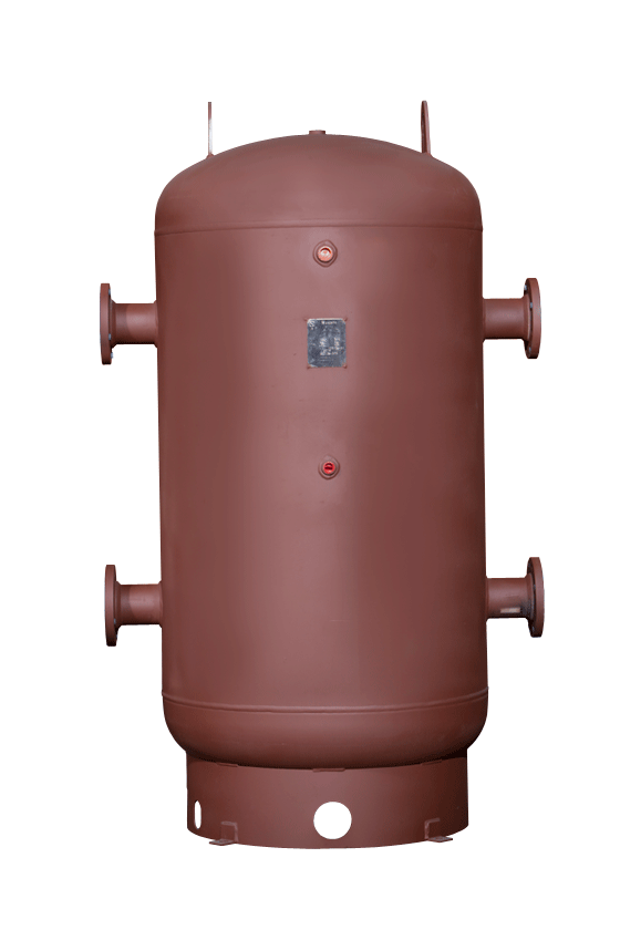
The Niles Steel Tank Hydraulic Separator is designed to help reduce short cycling of a boiler system and separate building and boiler circulation. It uses stored boiler water to buffer the system load when the boiler is producing more BTU’s than what the building can handle. When the building has a minimal demand, it pulls from the tank allowing the boiler to “rest”.
Hydraulic Separators

how it operates:

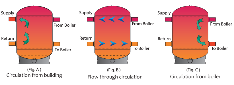
When the building’s hydronic system has a demand for heat, the building’s circulation pumps pull from the hydraulic separator (fig A.) until there is enough temperature drop in the tank to activate the boiler. When this occurs, both boiler and building’s circulation pumps are activated allowing direct flow through the tank (Fig. B ). As the building’s demand is satisfied and its circulation pumps are stopped, there is still a demand in the tank to return it to its operating temperature (Fig. C ). The boiler will continue to circulate and fire until the tank’s temperature is satisfied.
sizing & selection:
Ordering a Hydraulic Separator with proper capacity involves 4 variables are needed:
- Minimum “run time” of the boiler. Check with your boiler equipment manufacturer for their recommended minimum run time.
- Minimum BTU output (BTU/hr). Based on the boiler output at the minimum firing rate, if equipped with a variable input system that modulates the firing rate down as the demand decreases.
- Minimum system (heat) load (BTU/hr). Based on the smallest zone calling for heat.
- Tank delta T for allowable temperature rise. For hydronic heating systems, typically allow between 10 and 40 degree rise in tank temperature.
- V = Tank volume
- T = Min. boiler run time
- MBO = Minimum Boiler Output (btu/ hr)
- MHL = Minimum Heat Load
- Delta T = Tank temp rise (degrees F)


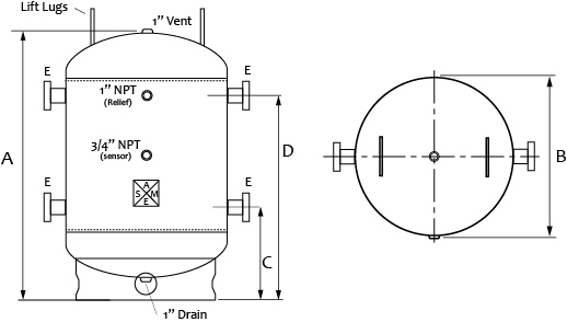
| Model | ActualGallons | NominalGallons | A | B | C | D | E |
|---|---|---|---|---|---|---|---|
| SEP-18-041 | 40 | 45 | 45″ | 18″ | 14.25″ | 33.75″ | 2″ NPT |
| SEP-24-045 | 80 | 88 | 49″ | 30″ | 16.75″ | 36.25″ | 3″ NPT |
| SEP-30-045 | 120 | 138 | 49″ | 30″ | 16.75″ | 36.25″ | 3″ NPT |
| SEP-30-075 | 210 | 229 | 79″ | 30″ | 16.75″ | 62.25″ | 3″ NPT |
| SEP-36-072 | 285 | 318 | 76″ | 36″ | 24.5″ | 55.5″ | 4″ FLG |
| SEP-42-072 | 385 | 432 | 76″ | 42″ | 27″ | 53″ | 6″ FLG |
| SEP-42-084 | 453 | 504 | 87″ | 42″ | 27″ | 64″ | 6″ FLG |
| SEP-48-096 | 675 | 752 | 100″ | 48″ | 29″ | 75″ | 6″ FLG |
| SEP-48-120 | 860 | 940 | 124″ | 48″ | 29″ | 99″ | 6″ FLG |

 #nilessteeltank