Heat Load – ________Btu (Boiler output)
Fluid – water/steam
Inlet temperature ____˚F
Outlet temperature ____˚F
Flow Rate __________ gpm
Tank Side:
Tank fluid – water/steam
Inlet temperature ____˚F
Outlet temperature ____˚F
Recovery Rate _______ gph
Heat Load – ________Btu (Boiler output)
Fluid – water/steam
Inlet temperature ____˚F
Outlet temperature ____˚F
Flow Rate __________ gpm
Tank Side:
Tank fluid – water/steam
Inlet temperature ____˚F
Outlet temperature ____˚F
Recovery Rate _______ gph

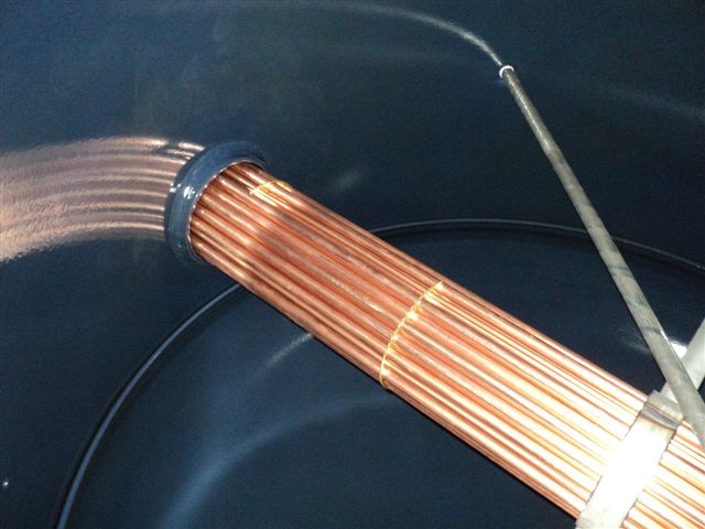
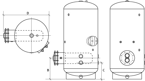
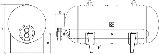
Niles Steel Tank offers both single wall and double wall heat exchangers. Please let us know which you need when submitting your request for bundle sizing. The drawings below are for general layout purposes. Actual submittal drawings can be provided once we know the scope of your project. Please use the diamensions below as an aid in the building layout.

Vertical Tanks
| Tank Diameter | Coil Diameter Dimension B |
Dimensions | ||||||
| 8″ | 10″ | 12″ | 14″ | C | D | |||
| 30 | 21 | 22 | n/a | n/a | 171⁄2 | 473⁄4 | ||
| 36 | 233⁄8 | 243⁄8 | n/a | n/a | 19 | 533⁄4 | ||
| 42 | 237⁄8 | 247⁄8 | 257⁄8 | 261⁄2 | 201⁄2 | 593⁄4 | ||
| 48 | 257⁄8 | 267⁄8 | 277⁄8 | 281⁄2 | 22 | 653⁄4 | ||

Horizontal Tanks
| Tank Diameter | Coil DiameterDimension B | Dimensions | ||||||
| 8″ | 10″ | 12″ | 14″ | C | D | |||
| 30 | 181⁄2 | 193⁄4 | 213⁄8 | n/a | 39 | 173⁄4 | ||
| 36 | 191⁄8 | 201⁄2 | 217⁄8 | 231⁄2 | 45 | 173⁄4 | ||
| 42 | 193⁄4 | 21 | 221⁄2 | 24 | 51 | 173⁄4 | ||
| 48 | 203⁄8 | 215⁄8 | 231⁄8 | 265⁄8 | 57 | 173⁄4 | ||
NOTES:
1. Standard materials for potable tank water include copper tubes, 316L stainless steel tube sheets, and spacers and cast iron heads.
2. For construction materials other than standard, consult factory.
3. An additional tube sheet present in double wall units is not shown in these layouts
4. Dimensions shown represent 125 PSI standard tank construction. For additional dimensional information, consult the factory.
5. Clearance should be provided at installation to permit coil removal and access to the manway if required.